
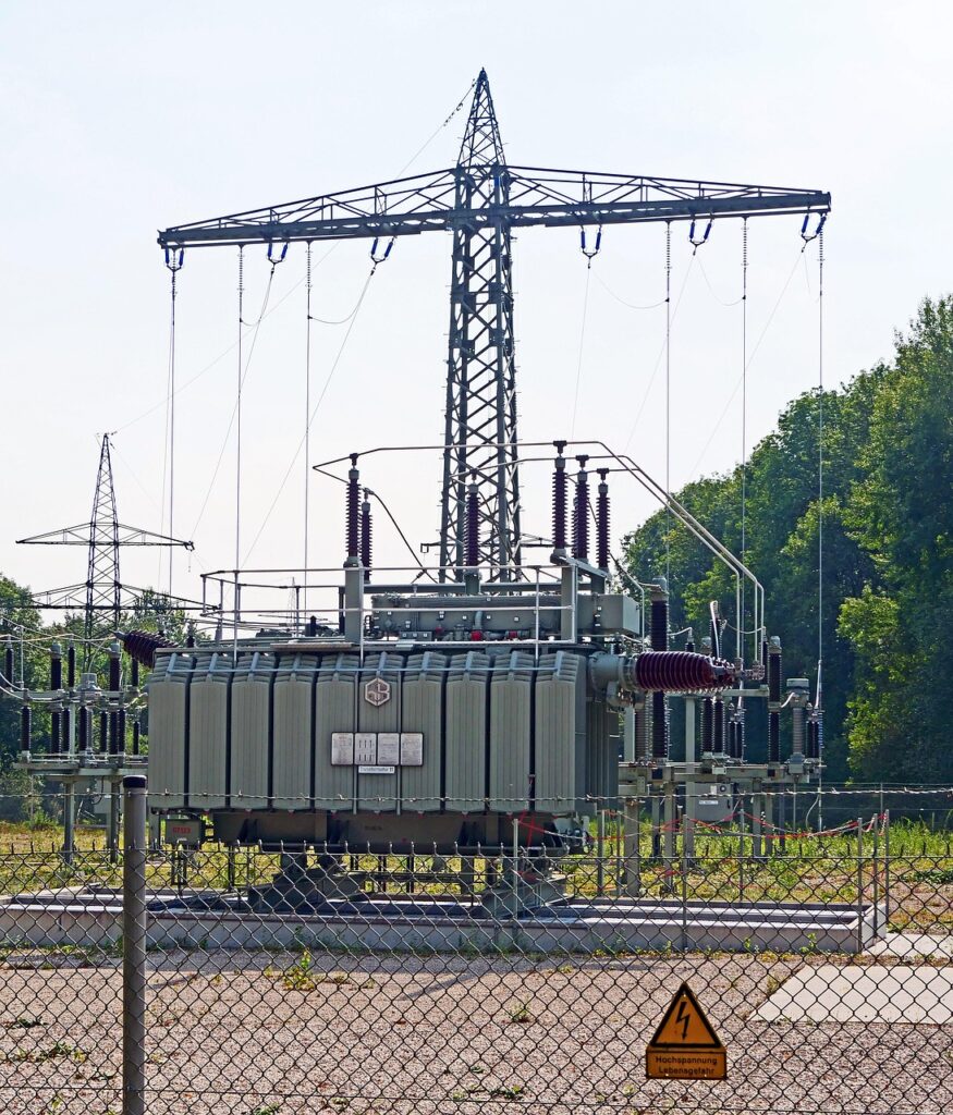
7 critical considerations for medium-voltage transformer substation installation in industrial facilities. IEC standards, protection coordination, and commissioning guide.
7 Critical Points to Consider in Medium-Voltage Transformer Substation Installation
Uninterrupted and safe power supply is vital for operational continuity in industrial facilities. Medium-voltage (MV) transformer substations serve as the heart of this electrical infrastructure. Poor design or faulty installation can lead to catastrophic equipment damage, costly production downtime, and severe occupational safety hazards.
Drawing on over 25 years of engineering expertise, this guide outlines the most common pitfalls and critical considerations in MV transformer substation installation.
What Is a Transformer Substation?
An MV transformer substation is an electrical installation equipped with protection systems that steps down medium-voltage power received from the grid (typically 10 kV or 34.5 kV) to low voltage (400 V) and distributes it to the main distribution switchboard.
Substations are primarily implemented in two structural configurations: Compact Transformer Substations (KTM) or Conventional (Indoor Masonry) Substations.
1. Accurate Power Calculation and Capacity Planning
Transformer capacity (kVA) must be calculated by accounting for not only existing loads but also future expansion plans.
Key considerations include:
Calculating real demand loads using demand and diversity factors
Assessing the impact of non-linear harmonic loads on transformer de-rating
Provisioning a 20% to 30% reserve power capacity
Determining power factor correction and compensation requirements
Under-sizing capacity leads to excessive transformer heating, reduced efficiency, and premature equipment failure.
2. Short-Circuit Calculation and Protection Coordination
Calculating prospective short-circuit currents and configuring protective relays accordingly is mandatory to ensure safe substation operation.
Required engineering steps:
Performing short-circuit analysis using ETAP or equivalent power system software
Setting protection thresholds for MV switchgear circuit breakers
Selecting low-voltage fuses and circuit breakers
Establishing selective protection coordination (discrimination)
Improper protection coordination can cause a single localized fault to trip the entire facility.
3. Transformer Room Design and Ventilation
Improperly designed transformer rooms lead to thermal buildup, degrading transformer performance and creating severe fire hazards.
Per applicable engineering standards:
Minimum ceiling height: 3.0 meters
Adequate intake and exhaust ventilation openings
Fire-rated doors and walls (REI 60 minimum)
Oil containment pit for liquid-filled transformers
IP54 enclosure protection if dry-type transformers are selected
4. Grounding and Equipotential Bonding
Grounding systems in MV installations are critical for both equipment protection and human safety.
Key implementation requirements:
Grounding grid design compliant with IEC 61936
Ground resistance measurements (targeting $\le 1\ \Omega$)
Calculation of touch and step voltage limits
Application of Neutral Grounding Resistors (NGR) where applicable
Bonding all metallic enclosures to the equipotential busbar
5. MV Cable Selection and Laying Techniques
Selecting and laying MV cables is a specialized engineering process.
Key considerations include:
Conductor cross-section selection and cable insulation type (XLPE, EPR)
Cable routing and adherence to minimum bending radii
Cable jointing and termination techniques
Minimum burial depth for underground installations (80 cm)
Mandatory cable testing: Very Low Frequency (VLF) hipot testing and partial discharge testing
Defective cable jointing remains the single most common cause of long-term MV cable failures.
6. Protective Relays and SCADA Integration
Deploying digital protection relays and remote monitoring systems in modern substations enhances both operational safety and plant efficiency.
Recommended practices:
Integration of digital protection relays from manufacturers like Siemens, Schneider Electric, or ABB
Calculation, setting, and formal documentation of relay curves
Integration with SCADA/RTU systems for real-time telemetry
Event logging and fault disturbance analysis
Establishing a periodic relay testing schedule
7. Commissioning Tests and Documentation
Commissioning represents the final and most critical phase of substation installation.
Mandatory pre-energization tests:
Insulation resistance testing (Megger test)
Transformer turns ratio and polarity testing
Mechanical and electrical interlock testing on MV switchgear
Secondary injection and functional testing of protection relays
Grounding system resistance measurements
Thermal monitoring under load
All test results must be documented and compiled into the final As-Built project documentation package delivered to the client.
Legal and Regulatory Mandates
MV transformer substation installations in Turkey must comply with the following regulatory frameworks:
Regulation on Electrical High-Current Installations (EKAT)
IEC 61936-1 — Power Installations Exceeding 1 kV AC
IEC 62271 — High-Voltage Switchgear and Controlgear
TEDAŞ Technical Specifications
Occupational Health and Safety Law No. 6331
MV facilities must be constructed under the direct supervision of an authorized electrical engineer, pass inspection by TEDAŞ or the local distribution utility, and formally appoint a Person in Charge of Operations.
Periodic Maintenance and Operations
Routine maintenance must not be neglected once the substation is commissioned:
Quarterly (Every 3 Months): Visual inspections and parameter monitoring
Annually: Protection relay testing and insulation resistance testing
Triennially (Every 3 Years): Comprehensive maintenance, cable diagnostic testing, and transformer oil analysis
⚠️ Legal Notice and Disclaimer
The technical details, statutory references, and engineering standards cited in this article are provided solely for general informational purposes. Applicable regulations, technical specifications, and standards in Turkey are subject to updates. You are required to verify current provisions directly through official resources, including the Official Gazette, TEDAŞ, EMRA (EPDK), the Ministry of Labour and Social Security, and recognized standards organizations (TSE, IEC, IEEE).
Every industrial facility possesses unique infrastructure constraints, operational conditions, and site requirements. Consequently, no technical information contained herein should be interpreted as a definitive engineering recommendation or directly executed without site-specific engineering analysis.
AYÇE Endüstriyel Makina İnşaat Elektrik Taahhüt San. ve Tic. Ltd. Şti. disclaims all liability for any direct, indirect, financial, or legal damages arising from the implementation of the information presented above. Always engage an authorized electrical engineer or consultant to manage your substation installation and compliance requirements.